OK…so how does the pilot determine the correct distance from the AOP? A little bit of technique and a lot of ‘That looks about right!” When a new fighter pilot first goes to the bombing range, his instructor will have shown him ground references to use for determining this distance. This position prior to the roll in is called the base leg….and can be thought of as very similar to the base leg in the traffic pattern back at your airfield. Sometimes ground references are not available or practical. In this case, the pilot is going to have to look outside at the AOP/target area and estimate the correct dive angle. The following figure shows how it looks when looking out of the side of your canopy at the target area. The pilot uses the horizon as his level flight reference and then estimates angles below the horizon. If necessary, the pilot will climb or descend on the base leg to get the desired look down angle.

Fig 7 – Dive Angle Estimation
I’ll stop for a second and re-emphasize that our dive angle intersects the ground at the AOP, not the target. Therefore, we have to use the AOP as the reference for base leg distance…not the target. If I’m repeating myself, it’s intentional! This can be confusing, and I want to avoid that at all costs! Think of it this way. Right now, in this discussion, we don’t know exactly where the AOP is, other than it’s somewhere past the target. Yes, we can compute the target to AOP distance in feet, but that won’t do us much good in the cockpit. So, what I’m eventually going to lead you to is a way to identify the AOP from the cockpit.
Let’s summarize where we are so far. We began with the distance from the AOP to the release point. Then, we computed the distance from the release point to the roll out point. To get ourselves established on a proper base leg, we need one more number, and that is the approximate turn radius of our turn from the base to the final. This number varies widely with pilot technique…some folks fly a lazy roll in, while others really honk it around. It’s a personal thing. I used to figure about 2,000-3,000 feet in the A-10…maybe a bit more in a F-16. Whatever the number you decide to use, this number is added to the roll out point to get your base leg distance.

Fig 8 – Roll In Radius
But how do we visualize this roll in point? First of all, a diagram showing the top view of the roll in. If we generalize about our roll in radius, we can approximate the roll in lead point by using clock positions relative to our nose and wingline. Each pilot’s roll in technique will be different, but a good starting point is to begin the turn as the target moves to your 10 or 2 o’clock position.
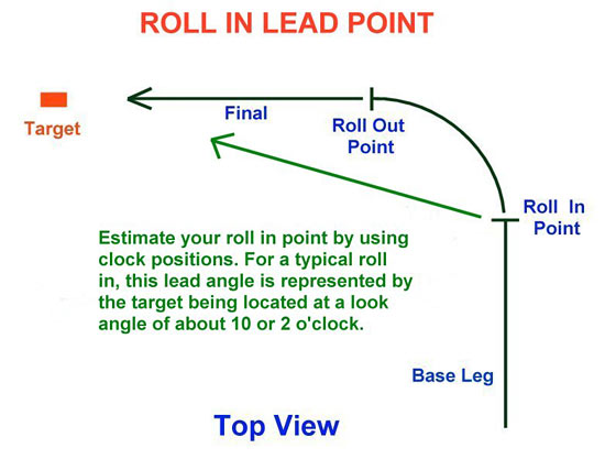
Fig 9 – Roll In Lead Point
Here’s a screenshot to show the technique. Notice the canopy rail and bow position. The pilot uses his 9 o’clock as his reference and then maintains his base leg position until the target moves back to his 10 o’clock. This is his roll in point.

Fig 10 – Roll In Clock Position
Lastly, since the roll in turn is a descending turn, we need to include a figure for the altitude lost in this turn. Let’s visualize our roll in triangle. The ground distance leg is derived from our turn radius, and we can use trig again to compute the altitude leg. But I want to simplify this a bit. Rather than go through the math again, I’ll use a WAG for estimating the altitude portion of the roll in (WAG…a wild a** guess!). For dive angles up to 30 degrees, I use about one half of the turn radius, and for dive angles greater than 30 degrees, I use about three-quarters of the turn radius.
All right!! It’s time to put away our trig tables and calculators. We’ve done the hard work. We now have a defined roll in point to begin our attack…a point in the sky that is a specific distance and altitude from our AOP. Earlier, I mentioned putting some bucks into the bank…well, you are there! The roll in point is your deposit box…what you put into it is how much you have to spend. Don’t short change the roll in point…the result will be not what you want or expect. With that firmly in hand, let’s move on to getting back into the cockpit.
Related Posts:
Related posts:
 Air To Ground Basics – Bombing
 Page 6
Air To Ground Basics – Bombing Page 7
Air To Ground Basics – Bombing Page 8
Air To Ground Basics – Bombing
Air To Ground Basics – Bombing Page 6
Air To Ground Basics – Bombing Page 7
Air To Ground Basics – Bombing Page 8
 Air To Ground Basics – Bombing, Part Two Page 2
Air To Ground Basics – Bombing, Part Two Page 3
Air To Ground Basics – Bombing, Part Two Page 7
Air To Ground Basics – Bombing, Part Two Page 8
Air To Ground Basics – Bombing, Part Two Page 2
Air To Ground Basics – Bombing, Part Two Page 3
Air To Ground Basics – Bombing, Part Two Page 7
Air To Ground Basics – Bombing, Part Two Page 8